 *
*

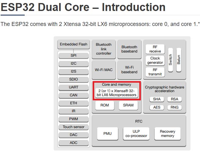
The ESP32 comes with 2 Xtensa 32-bit LX6 microprocessors: core 0 and core
1. So, it is dual core. When we run code on Arduino IDE, by default, it runs on core
1. In this tutorial, we’ll show you how to run code on the ESP32 second core by creating FreeRTOS tasks.
You can run pieces of code simultaneously on both cores, and make your ESP32 multitasking.
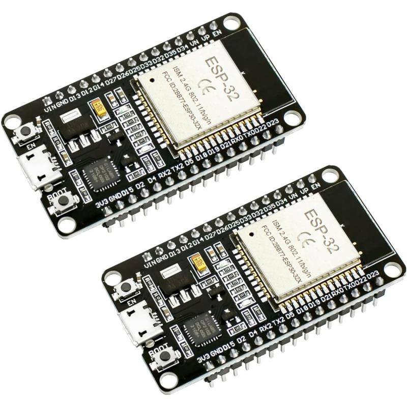
* some specific ESP32 models are not dual-core. Check the ESP32 board you’re using before following this tutorial.
Here are some of the most popular models that are not dual core:
-
Based on ESP32-S2:
- ESP32-S2-Saola-1 (Espressif dev board)
- ESP32-S2-Kaluga-1 (Multimedia dev kit with display/camera support)
-
Based on ESP32-C3:
- ESP32-C3-DevKitM-1 (Espressif mini dev kit)
- ESP32-C3-WROOM-0
- Seeed Studio XIAO ESP32-C3
- Waveshare ESP32-C3-Zero
-
Based on ESP32-C6:
- ESP32-C6-DevKitC-1 (Espressif dev board)
- Seeed Studio XIAO ESP32-C6
-
Based on ESP32-H2:
- ESP32-H2-DevKitM-1
By default, when we run code on the ESP32, it runs on core
1. When we upload code to the ESP32 using the Arduino IDE, it just runs – we don’t have to worry about which core executes the code.
There’s a function that returns in which core the code is running:
xPortGetCoreID()
If you use that function in an Arduino sketch, you’ll see that both the setup() and loop() are running on core
1. Test it yourself by uploading the following sketch to your ESP32.
void setup() {
Serial.begin(115200);
Serial.print("setup() running on core ");
Serial.println(xPortGetCoreID());
}
void loop() {
Serial.print("loop() running on core ");
Serial.println(xPortGetCoreID());
}
To assign specific parts of code to a specific core, you need to create tasks.
When creating a task, you can choose which core it will run in, as well as its priority.
Priority values start at 0, which 0 is the lowest priority.
The processor will run the tasks with higher priority first. To create tasks, you need to follow the next steps:
To create tasks, you need to follow the next steps:
1. Create a task handle. An example for Task1:
TaskHandle_t Task1;2. In the setup() create a a task assigned to a specific core using the
xTaskCreatePinnedToCore function. That function takes several arguments,
including the priority and the core where the task should run (the last parameter).
xTaskCreatePinnedToCore( Task1code, /* Function to implement the task */ "Task1", /*
Name of the task */ 10000, /* Stack size in words */ NULL, /* Task input parameter */ 0, /*
Priority of the task */ &Task1, /* Task handle. */ 0); /* Core where the task should run */
3. After creating the task, you should create a function that contains the code for the created task. In this example,
you need to create the Task1code() function. Here’s how the task function looks like:
Void Task1code( void * parameter) { for(;;) { Code for task 1 - infinite loop (...) } }The for(;;) creates an infinite loop. So, this function runs similarly to the loop() function. You can use it as a second loop in your code, for example.
If during your code execution you want to delete the created task, you can use the vTaskDelete()function, that accepts the task handle (Task1) as argument:
vTaskDelete(Task1);
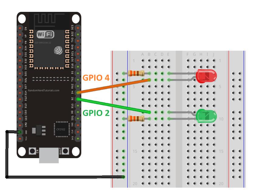
Upload the next sketch to your ESP32 to blink each LED in a different core:
/*********
  Rui Santos
  Complete project details at https://randomnerdtutorials.com

	*********/ TaskHandle_t Task1; TaskHandle_t Task2; // LED pins const int led1 = 2; const int led2 = 4;


	void setup() { Serial.begin(115200); pinMode(led1, OUTPUT); pinMode(led2, OUTPUT);


	//create a task that will be executed in the Task1code() function,


	with priority 1 and executed on core 0 xTaskCreatePinnedToCore


	( Task1code, /* Task function. */ "Task1", /* name of task. */ 10000,


	/* Stack size of task */ NULL, /* parameter of the task */ 1, /* priority of the task */ &Task1,


	/* Task handle to keep track of created task */ 0); /* pin task to core 0 */ delay(500);


	//create a task that will be executed in the Task2code()


	function, with priority 1 and executed on core 1 xTaskCreatePinnedToCore


	( Task2code, /* Task function. */ "Task2", /* name of task. */ 10000, /* Stack size of task */


	NULL, /* parameter of the task */ 1, /* priority of the task */ &Task2, /*


	Task handle to keep track of created task */ 1); /* pin task to core 1 */ delay(500); }


	//Task1code: blinks an LED every 1000 ms void Task1code( void * pvParameters )


	{ Serial.print("Task1 running on core "); Serial.println(xPortGetCoreID()); for(;;)


	{ digitalWrite(led1, HIGH); delay(1000); digitalWrite(led1, LOW); delay(1000); } }


	//Task2code: blinks an LED every 700 ms void Task2code( void * pvParameters )


	{ Serial.print("Task2 running on core "); Serial.println(xPortGetCoreID()); for(;;)


	{ digitalWrite(led2, HIGH); delay(700);


	digitalWrite(led2, LOW); delay(700); } } void loop() { }
How Does the Code Work?
Note: in the code, we create two tasks and assign one task to core 0 and another to core 1. Arduino sketches run on core 1 by default.
So, you could write the code for Task2 in the loop()
(there was no need to create another task). In this case we create two different tasks for learning purposes.
But, depending on your project requirements,
it may be more practical to organize your code in tasks as demonstrated in this example.
The code starts by creating a task handle for Task1 and Task2 called Task1 and Task2.
TaskHandle_t Task1; TaskHandle_t Task2;Assign GPIO 2 and GPIO 4 to the LEDs:
const int led1 = 2; const int led2 = 4;In the setup(), initialize the Serial Monitor at a baud rate of 115200:
Serial.begin(115200);Declare the LEDs as outputs:
pinMode(led1, OUTPUT); pinMode(led2, OUTPUT);Then, create Task1 using the xTaskCreatePinnedToCore() function:
xTaskCreatePinnedToCore( Task1code, /* Task function. */ "Task1", /* name of task. */ 10000, /* Stack size of task */ NULL, /* parameter of the task */ 1,
/* priority of the task */ &Task1, /* Task handle to keep track of created task */ 0); /* pin task to core 0 */
Task1 will be implemented with the Task1code()
function. So, we need to create that function later in the code. We give the task priority 1, and pinned it to core 0.
We create Task2 using the same method, but we assigned it to core 1:
xTaskCreatePinnedToCore( Task2code, /* Task function. */ "Task2", /* name of task. */ 10000,
/* Stack size of task */ NULL, /* parameter of the task */ 1, /*
priority of the task */ &Task2, /* Task handle to keep track of created task */ 1); /* pin task to core 0 */
After creating the tasks, we need to create the functions that will execute those tasks.
void Task1code( void * pvParameters ){ Serial.print("Task1 running on core ");
Serial.println(xPortGetCoreID()); for(;;){ digitalWrite(led1, HIGH);
delay(1000); digitalWrite(led1, LOW); delay(1000); } }
The function for Task1 is called Task1code() (you can call it whatever you want).
For debugging purposes, we first print the core in which the task is running:
Serial.print("Task1 running on core "); Serial.println(xPortGetCoreID());Then, we have an infinite loop similar to the loop() on the Arduino sketch. In that loop, we blink LED1 every one second.
The same thing happens for Task2, but we blink the LED with a different delay time.
void Task2code( void * pvParameters ){ Serial.print("Task2 running on core "); Serial.println(xPortGetCoreID());
for(;;){ digitalWrite(led2, HIGH); delay(700); digitalWrite(led2, LOW); delay(700); } }
Finally, the loop() function is empty:
void loop() { }Note: as mentioned previously, the Arduino loop() runs on core
1. So, instead of creating a task to run on core 1, you can write your code inside the loop().
But, it might be more practical to organize your code in FreeRTOS tasks.
Wrapping Up
In summary, in this tutorial, you learned that:
- Most ESP32 models are dual-core.
- Arduino sketches run on core 1 by default.
- To use core 0, you need to create FreeRTOS tasks.
- You can use the xTaskCreatePinnedToCore() function to pin a specific task to a specific core.
- Using this method, you can run two different tasks independently and simultaneously using the two cores.
In this tutorial, we’ve provided a simple example with LEDs.
The idea is to use this method with more advanced projects with real-world applications.
For example, it may be useful to use one core to take sensor readings and another to publish those readings on a home automation system.